Monday, May 27, 2013

Data Flow Diagrams (DFD) - Part II


There are only four different symbols that are normally used on a DFD. The elements represented are:

  • External entities
  • Processes
  • Data stores
  • Data flows
External entities

External entities are those things that are identified as needing to interact with the system under consideration. The external entities either input information to the system, output information from the system or both. Typically they may represent job titles or other systems that interact with the system to be built. Some examples are given below in Figure 1.  Notice that the SSADM symbol is an ellipse. If the same external entity is shown more than once on a diagram (for clarity) a diagonal line indicates this.

Processes

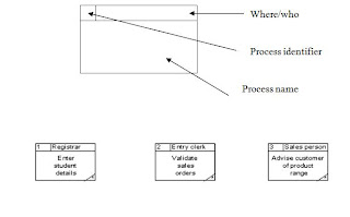
Processes are actions that are carried out with the data that flows around the system. A process accepts input data needed for the process to be carried out and produces data that it passes on to another part of the DFD. The processes that are identified on a design DFD will be provided in the final artefact. They may be provided for using special screens for input and output or by the provision of specific buttons or menu items. Each identifiable process must have a well chosen process name that describes what the process will do with the information it uses and the output it will produce. Process names must be well chosen to give a precise meaning to the action to be taken. It is good practice to always start with a strong verb and to follow with not more than four or five words.

Examples of good process names would be :

  • Enter customer details
  • Register new students
  • Validate sales orders
Try to avoid using the verb ‘process’, otherwise it is easy to use this for every process. We already know from the symbol it is a process so this does not help us to understand what kind of a process we are looking at.

Data stores

Data stores are places where data may be stored. This information may be stored either temporarily or permanently by the user. In any system you will probably need to make some assumptions about which relevant data stores to include. How many data stores you place on a DFD somewhat depends on the case study and how far you go in being specific about the information stored in them. It is important to remember that unless we store information coming into our system it will be lost.

Data flows

The previous three symbols may be interconnected with data flows. These represent the flow of data to or from a process. The symbol is an arrow and next to it a brief description of the data that is represented. There are some interconnections, though, that are not allowed.

These are:
  • Between a data store and another data store
    • This would imply that one data store could independently decide to send some of information to another data store. In practice this must involve a process.
  • Between an external entity and a data store
    • This would mean that an external entity could read or write to the data stores having direct access. Again in practice this must involve a process.
Also, it is unusual to show interconnections between external entities. We are not normally concerned with information exchanges between two external entities as they are outside our system and therefore of less interest to us.

DFD Example


Here are some key points that apply to all DFDs

  • All the data flows are labelled and describe the information that is being carried.
  • It tends to make the diagram easier to read if the processes are kept to the middle, the external entities to the left and the data stores appear on the right hand side of the diagram.
  • The process names start with a strong verb
  • Each process has access to all the information it needs. In the example above, process 4 is required to check orders. Although the case study has not been given, it is reasonable to suppose that the process is looking at a customer’s order and checking that any order items correspond to ones that the company sell. In order to do this the process is reading data from the product data store.
  • Each process should have an output. If there is no output then there is no point in having that process. A corollary of this is that there must be at least one input to a process as it cannot produce data but can only convert it form one form to another.
  • Data stores should have at least one data flow reading from them and one data flow writing to them. If the data is never accessed there is a question as to whether it should be stored. In addition, there must be some way of accumulating data in the data store in the first place so it is unlikely there will be no writing to the data store.
  • Data may flow from
    • External entity to process and vice-versa
    • Process to process
    • Process to data store and vice-versa
  • No logical order is implied by the choice of id for the process. In the example process id’s start at 4. There is no significance to this.
Drawing diagrams like this requires practice. You should not be unduly worried if your diagram does not look exactly like a colleague’s or a model answer. Systems analysis is very rarely done in isolation and you and your working partners and the user will come to some agreement about the final product.

Monday, May 13, 2013

Data Flow Diagrams (DFD) - Part I

This unit deals with one of the major techniques for recording the requirements of a user for a new computer application. An initial diagram is constructed to show the processes which are being implemented in an existing system. The diagram helps to show how information is used to produce the functions that are required by the current system. It also shows what information is provided to the system and what information is provided form the system. Other benefits include the documentation of who is using the system and what data will be stored. By careful construction of the DFDs (data flow diagrams) the boundaries of the system to be built may be clearly identified. This helps to clarify what will and what will not be constructed. It will also show the interaction that may be required with other systems.

The data flow diagrams should also have some associated documentation. This is necessary as the diagrams are meant as a visual representation of the way in which information is processed. There is limited space on the diagrams so that documentation to explain, refine and describe further details of what is shown need to be kept somewhere in the proposed system documentation. The data flow diagrams and the associated documentation together combine to form a data flow model. This is also commonly called a process model.

The user requirements when complete are used as a basis for the development of the system. Later when the system has been developed it can be tested against the initial requirements to see whether the user’s needs have been met.

Development and purpose of DFDs

Before attempting to construct an initial DFD it is necessary to gather and digest information that helps us to understand how data is processed in the current system. Fact-finding techniques are used for this purpose and are discussed in another Unit. As the DFD is constructed a systems analyst will often come across areas of doubt where the precise way to model the system is unclear. This is a natural part of the development and should not be regarded with alarm. In fact, it is expected and it is a consequence of attempting to model the current situation that questions will be asked to clarify the exact processes which are taking place. Sometimes the analyst will make an assumption and then check this with the user at a subsequent meeting.

Results of interviews, documents, reports, questionnaires etc. will all play a part in helping the analyst to gain an insight into the current processes. Where a system is being developed form scratch the analyst will work with the user to develop the proposed DFDs.

When all the information about the current system is gather it should be possible to construct the DFDs to show:
  • the information that enters and leaves the system
  • the people/roles/other systems who generate and/or receive that information
  • the processes that occur in the system to manipulate the information
  • the information that is stored in the system
  • the boundary of the system indicating what is (and what is not) included

As a staring point, it is sometimes useful to construct a document flow diagram. This diagram shows how ‘documents’ are passed around an organization to fulfill the current requirements of the system under investigation. The term’ documents’ is interpreted very loosely and usually translates to information.
Sometimes before beginning to produce the set of data flow diagrams a document flow diagram is generated. This helps to establish the system boundary so we can decide which parts of the system we are modelling and which parts we are not. The document flow diagram shows the different documents (or information sources in the system and how they flow from a source to a recipient.

Here is an example of a document flow diagram shown below.

Here ellipses represent either the source or recipient of the ‘documents’ and named arrows show the direction of transfer and the nature of the information being exchanged. This kind of diagram is a first step in understanding what information is in the system and how it is used to perform the required functions.

Another useful feature of the construction of this type of diagram is that it enables a sensible discussion of where the system boundary should lie. In other words it is important to establish what is to be included in the proposed information system and what is not. To indicate this, a system boundary line is constructed on the document flow diagram.


*** Please remember that drawing the system boundary is very very important.

Sunday, May 12, 2013

Methodologies

An engineering approach to building systems requires certain methods and tools to be used to ensure that systems are built in a most effective way. These kind of approach we call as methodologies. A methodology is a set of predefined rules and steps to build a system. Use of methodologies help us to build models of a system and verify requirements, etc. We should use a methodology when we are engaged in a team development environment. There are large number of tools available for different kind of methodologies.

Generally we can identify following methodologies in software system designing and development.
  • Hard System Methodology (HSM)
    • Structured Methodology 
      • SSADM (Structured System Analysis and Development Methodology) 
      • JSD (Jackson’s System Development) 
      • YSM (Yourdon’s Structured Methodology) 
    • Object Oriented Methodology 
      • OMT (Object Modeling Techniques) 
      • OOSE (Object Oriented Software Engineering) 
  • Soft System Methodology (SSM) 
  • Hybrid (HSM + SSM) 
  • Formal System Methodology


Hard System Methodology (HSM)

We use this method to develop systems that the problem definition is clear and the solution for the problem is therefore direct. So, we assume that there is a solution for the problem and we know what goals exactly to be achieved. You can identified the success and result prior to develop the system. “WHAT” kind of problem and “HOW” to solve it can be identified early in this methodology.

Structured System Analysis and Development Methodology (SSADM)
 
  • SSADM Process
    • Feasibility Study
    • Requirement Analysis
    • Requirement Specification
    • Logical System Specification
    • Physical Design
  • Modeling Languages
    • Techniques and Tools
    • Functional Sub-Modeling (DFD - Data Flow Diagrams)
    • Data Sub-Modeling (ERD - Entity Relationship Diagrams)
    • Dynamic Sub-Modeling (ELH - Entity Life History)

SSADM Process
  1. Feasibility Study - This will analyze and identify technical, operational and economical feasibility of the system.
  2. Requirement Analysis - Here we gather operational and dynamic user requirements from the new system. This process also include the analysis of the current system using DFD diagrams, etc.
  3. Requirement Specification - This is a document that explains the requirements of the new system using DFD, ERD and other diagrams.
  4. Logical System Specification - This will create a model / logical design of the intended new system by identifying various technical options. This is an implementation independent model.
  5. Physical Design - This step will convert the logical design of the system into an implementation dependent model.

SSADM Modeling Languages / Tools

There are three modeling tools available for modeling of functional, data and dynamic sub models.
  • DFD for Functional Sub Modeling
  • ERD for Data Sub Modeling
  • ELH for Dynamic Sub Modeling

Each of these sub models has its own view of the perspective of the system. Each concentrates on certain aspects and ignorance of others. By combining of these three models gives a whole picture of the new system.

Thursday, May 9, 2013

Data Collecting Techniques (Fact Finding Methods)

Data collecting is very important in the software development specially in the system analysis phase. There are four types of data collecting methods;

  1. Questionnaires
  2. Interviews
  3. Observations
  4. Report Inspection
Questionnaires:

 There are two types of questionnaires;
  1. Open questionnaires
  2. Closed questionnaired
In open questionnaires the respondent can write his / her describe the answer in details where as in the closed type questionnaires the respondent have to select an answer from a given set of selections. Closed type questionnaires are widely using because of its simplicity and easy to reach large number of respondents.

You have to Google for advantages and disadvantages of both open and closed type questionnaires. These are very important for the exam.

Interviews

Interviews are the main choice when we want to collect data from experts, especially when we need to get qualitative data. Interviews can take place in many forms. The most popular form is the face to face interviewing a person by the interviewer. One or interview panel can interview another one or a batch of interviewers. However in the software developments this is the most famous method of data collection.

You need to have a good understanding about advantages and disadvantages of interview method as well as interviewing types. Please Google!

Observations

 Observation is another method of fact finding specially when we want to understand business flows. In this method you are going to observe various details about the business process you want to document. You may collect information such as users involved in the process, kind of data used in the process, inputs and outputs, generated reports, problems, regulations, etc.

Report Inspection

This is the best method to collect historical data. You can use reports such as quotations, invoices, accounting journals, magazines, certifications, etc. In the software development we use this method in find out various formats, data and input/outputs used in the business process.

In the software development we would have to use one or many of these techniques in various phases throughout the development process. More information are available in the internet about fact finding techniques and it is very important for you to browse the web get gain the necessary knowledge requried with practical usage of these techniques.

Tuesday, May 7, 2013

Prototyping

A prototype is a model that describes features of a "thing". In regard to software systems, we can describes “prototype” is a system that describes interfaces and features of an intended system.

In the field of software development, prototyping is very important. Most of the time customers don’t know how to express their requirements and they have no idea about how the system will affect to their business. In the other hand, customer want to get an idea about how well the software company is understand their requirement. So, the customer and the software company will come to an agreement to develop a prototype of the system that describes the features (most of the time interfaces and functions) of the actual system. So, we can say that prototyping is a requirement validation of the customer. This helps to identify and omit errors prior to develop the actual system.

In software development prototyping, normally do not involve the programing, instead create a graphical representation only.

The objectives of prototyping should be made explicit from the start of the process. The objective may be to develop the system to validate functional system requirements or it may be develop to demonstrate the feasibility of the application  to manage, etc.

There are two types of prototyping.
  1.     Throw away prototypes
  2.     Evolutionary prototypes

Throw-away Prototypes

This is the most common type of prototyping. This type of prototypes are used to validate requirements and understand the system correctly and throw away the prototype and start developing the actual system from scratch.

Advantages of Throw-Away prototypes.
  •     Both functions and non-functions are satisfied.
  •     Easy to do modifications as customer feedback
  •     Reduce the risk factor
  •     Able to create a good system specification
  •     Future maintenance is easy

Disadvantages of Throw-away prototypes.
  •     Expensive method, because you need to develop two systems.
  •     Consumes lot of time
  •     Waste of resources because you throw away the prototype

Evolutionary Prototypes

In this method, the prototype will be developed into the final system going through many stages with the customer feedback. The prototype and production processes are merged. This is important when initializing user requirements are extremely difficult.

Advantages of Evolutionary Prototypes.
  •     Accelerated delivery of the system
  •     User engagement with the system is very high

Disadvantages of Evolutionary Prototypes.
  •     Only functional requirements are satisfied
  •     Non-functional requirements such as security, reliability, performance may not be satisfied.

Sunday, May 5, 2013

RAD (Rapid Application Development) Model


Rapid Application Development (RAD) is an incremental software development process model that emphasizes an exactly short development cycle. The RAD model is a "high speed" adaptation of the linear sequential model in which rapid development is achieved by using component based construction. If requirements are well understood and project scope is constrained the RAD process enables a development team to create a "fully functional system" within very short time period.

Business Modeling: The information flow among business function is modeled in a way that answer the following questions. What information drives the business process? What information is generated? Who generates it? Where does the information go? Who process it?

Data Modeling: Information flow defined as part of the business modeling phase is refined into a set of data objects to support the business. The characteristics (called attributes) of each objects are identified and the relationship between these objects defined.

Process Modeling: The data objects defined in the data modeling phase are transformed to achieve the information flow necessary to implement a business function. Process descriptions are created to adding, modifying, deleting or retrieving a data object.

Application Generation: RAD assumes the use of fourth generation techniques. Rather than creating software using conventional third generation programming languages the RAD process works to reuse existing program components (when necessary) in all cases, automated tools are used to facilitate construction of the software.

Testing and Turnover: Since the RAD process emphasize the reuse many of the program components have already been tested. This reduce overall testing time. However new components must be tested and all interfaces must be fully exercised.

The time constrained imposed on a RAD project demand "scalable scope". If a business application can be modularized in a way that enables each major function to be completed in less that three months, it is a candidate for RAD. Each major function can be addresses by a separate RAD team and then integrated to form a whole.

Important Notice!

Dear students and friends. When you commenting please do not mention your email address. Because your email address will be publicly available and visible to all. Soon, it will start sending tons of spams because email crawlers can extract your email from feed text.

To contact me directly regarding any inquiry you may send an email to info@bcslectures.website and I will reply accordingly.